Key Features
Compact Design
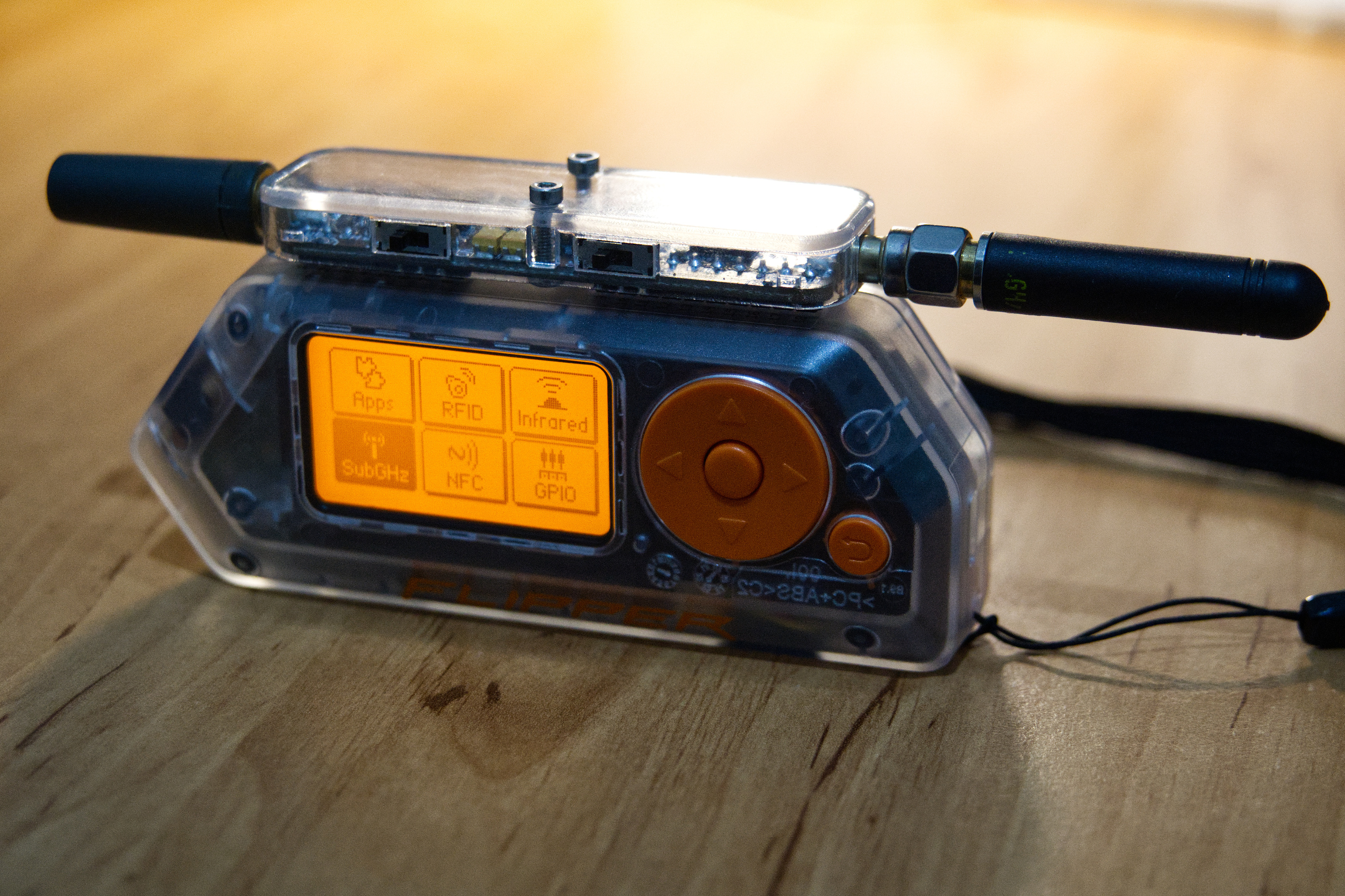
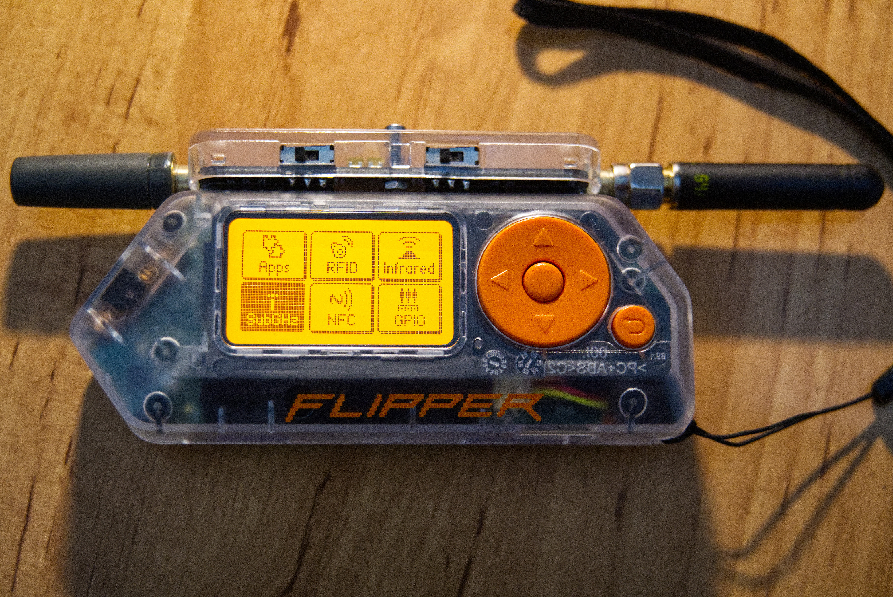
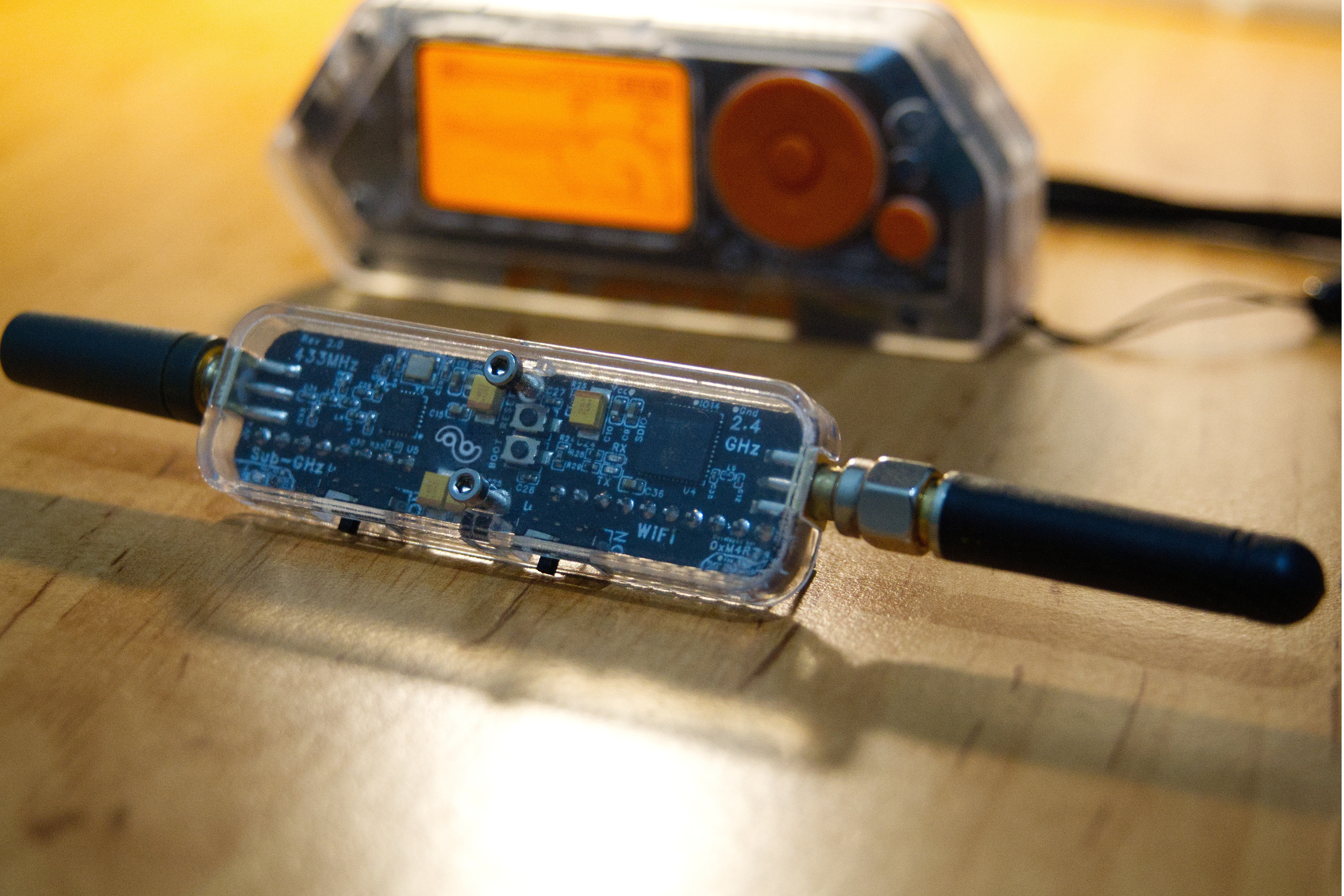
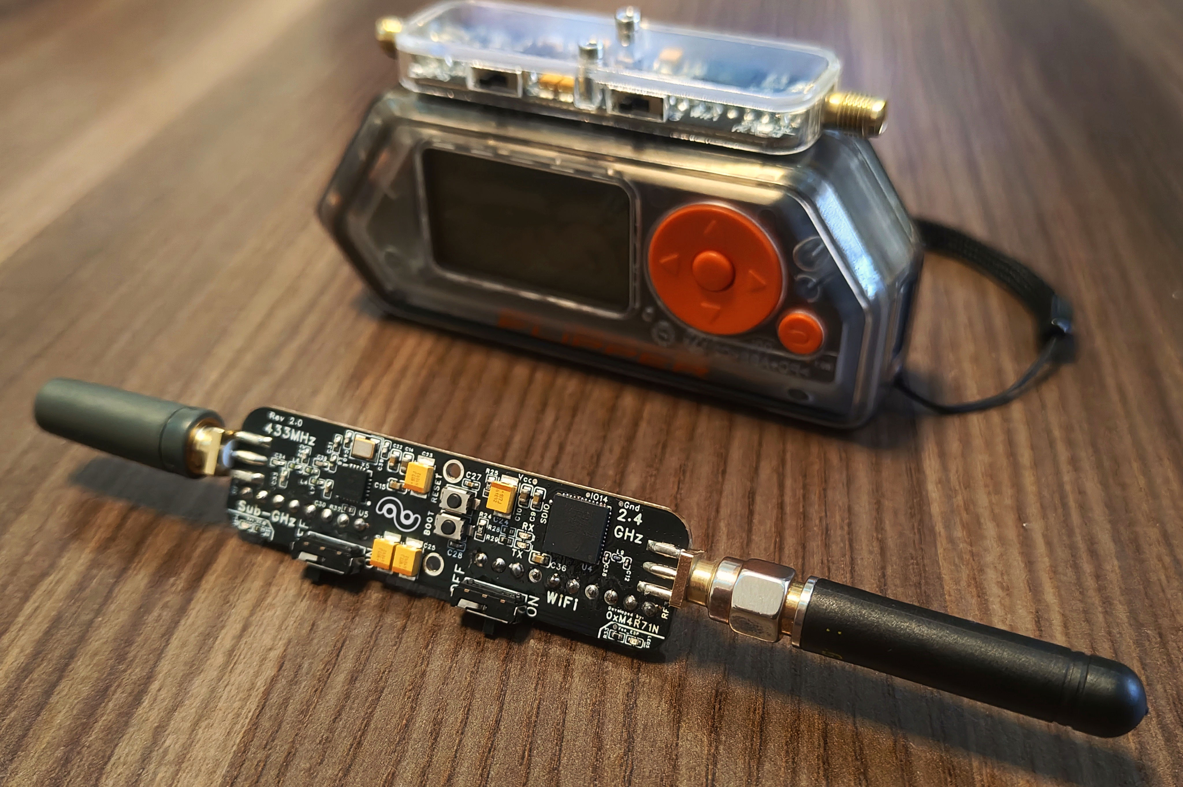
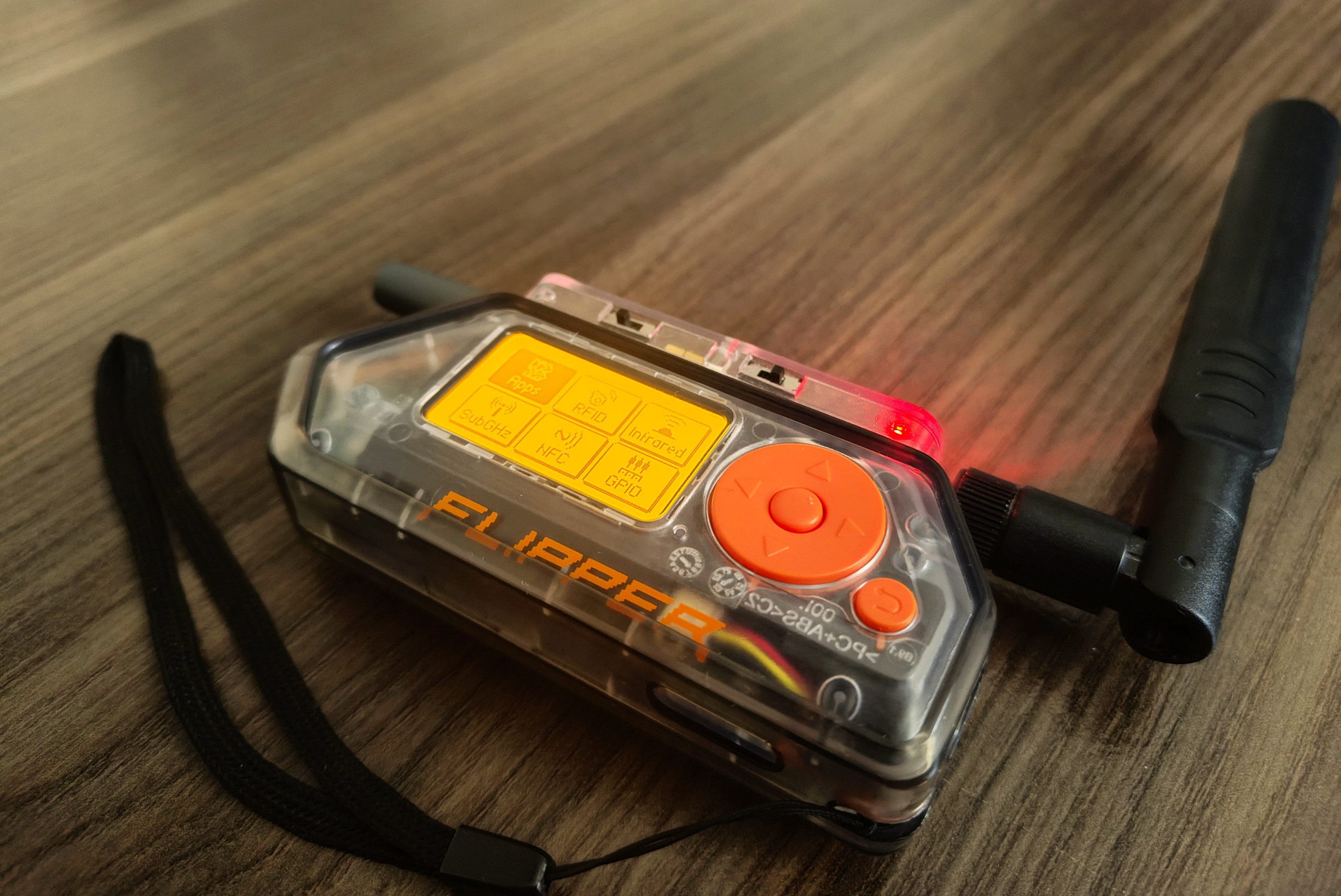
Plug directly into Flipper Zero's GPIO header. Designed for permanent attachment with compact form factor - compactness was the key motivation behind development.
Dual Radio System
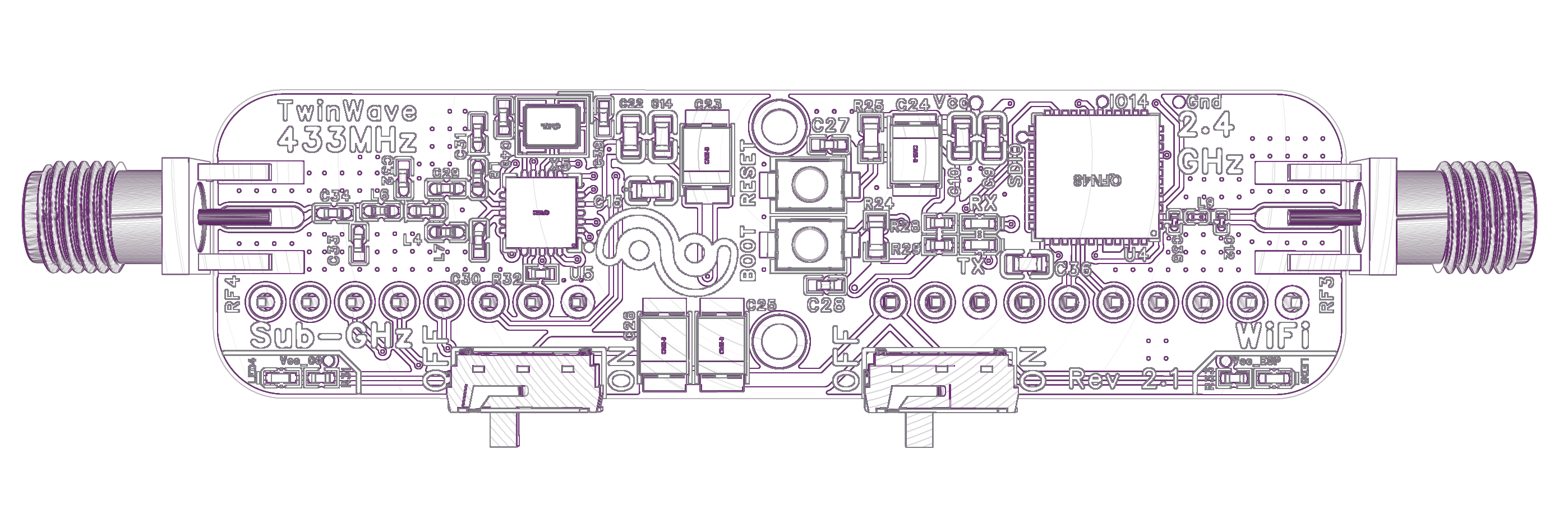
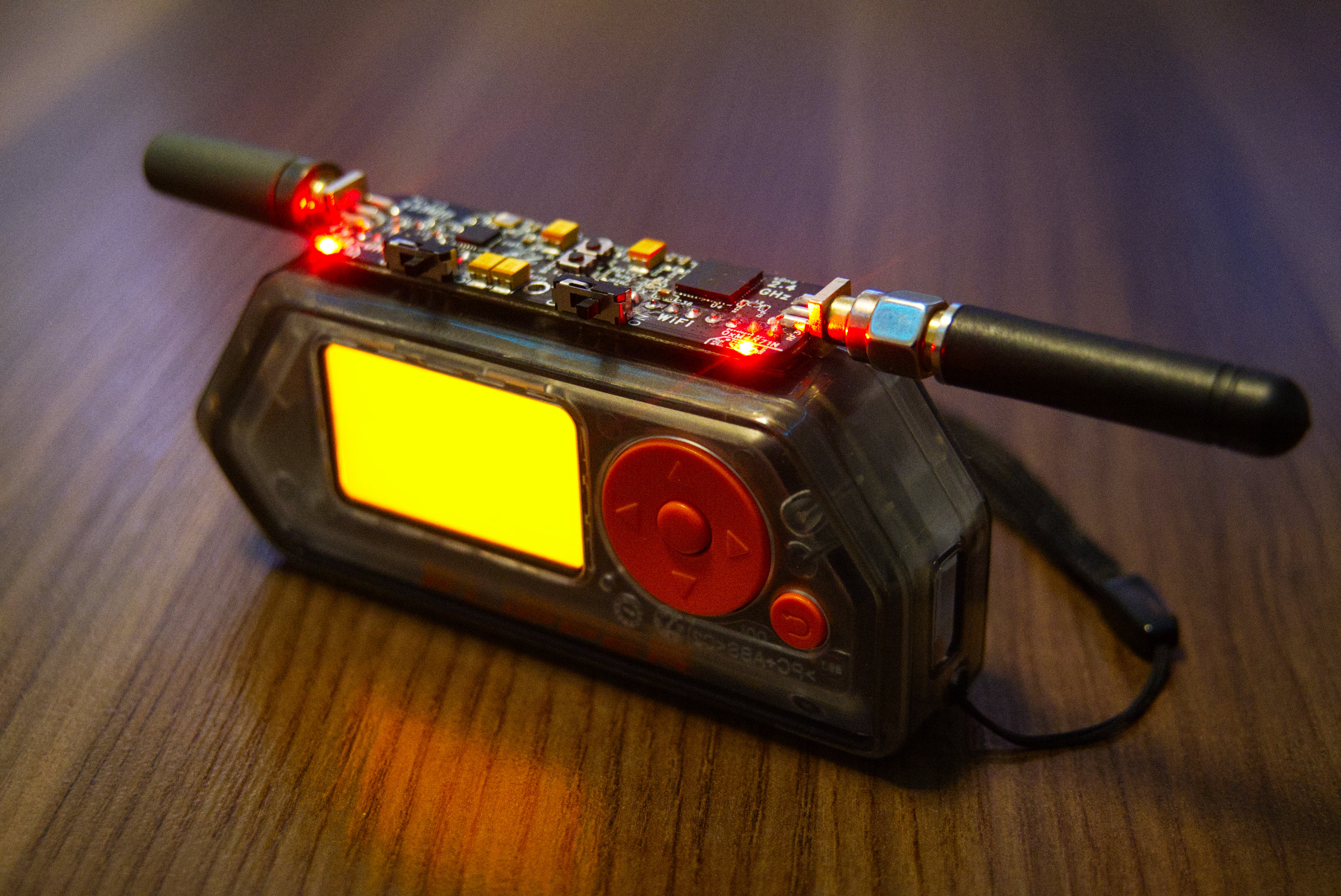
Wi-Fi 2.4 GHz (ESP32-PICO-V3-02) + Sub-GHz 433 MHz (TI CC1101) in one compact module.
Replaceable Antennas
2× SMA female connectors allow you to swap antennas for optimal performance in any scenario.
Marauder Firmware
WiFi analysis, traffic monitoring, and wireless penetration testing with Marauder firmware.
Independent Power Control
Micro switches for Wi-Fi and Sub-GHz radios. Save battery by disabling unused modules.
Community Open Hardware
Transparent design with complete schematics and PCB files. Free to build, study, and customize for personal use.
Gallery
Product Photos
Demo Video
Technical Specifications
| Parameter | Specification |
|---|---|
| Wi-Fi Radio | ESP32-PICO-V3-02 (2.4 GHz) |
| Sub-GHz Radio | TI CC1101 (433 MHz) |
| Antenna Connectors | 2× SMA Female |
| Power Supply | 3.3V via Flipper GPIO |
| Power Consumption (Sub-GHz) | 20-40 mA |
| Power Consumption (Wi-Fi Idle) | ~40 mA |
| Power Consumption (Wi-Fi Active) | 125-330 mA |
| ESP32 Interface | UART/Serial via GPIO |
| CC1101 Interface | SPI Bus (shared with Flipper) |
| Firmware Support | Marauder v1.12.1 (ESP32 PICO port) |
| PCB Revision | v2.1 |
Firmware Upload
To upload or update the ESP32 Marauder firmware, you need to connect via a USB-TTL (UART) adapter to the GPIO pin header on the bottom side of the TwinWave PCB.
UART Connection (10-pin header - bottom side)
Connect USB-TTL adapter (CP2102, CH340, FT232) to the 10-pin GPIO header on the bottom side of TwinWave PCB:
| Pin 1 (3V3) | → | VCC (3.3V only!) |
| Pin 3 (GND) | → | GND |
| Pin 5 (RX) | → | TX (adapter) |
| Pin 6 (TX) | → | RX (adapter) |
Hold BOOT, press RESET, release both to enter flash mode.
Web Flasher (Recommended)
Flash firmware directly from your browser — no installation required!
- Connect USB-TTL adapter to TwinWave
- Put ESP32 into boot mode (hold BOOT, press RESET, release both)
- Open the Web Flasher and follow the wizard
Downloads
Download all necessary files for manufacturing your own TwinWave module from the latest GitHub release.
Pin Header Assembly: It is recommended to assemble the pin header yourself (GPIO connector). This allows you to adjust the pin length to perfectly fit your specific Flipper Zero configuration - whether it has a protective case or not.
PCB Manufacturing
Gerber, BOM and Pick & Place files for PCB fabrication services (JLCPCB, PCBWay, etc.)
PCB Stackup: JLC04161H-7628
| Top Layer | Copper 0.035mm |
| Prepreg | 7628×1 (0.21mm) |
| Inner L2 | Copper 0.0152mm |
| Core | 1.065mm |
| Inner L3 | Copper 0.0152mm |
| Prepreg | 7628×1 (0.21mm) |
| Bottom Layer | Copper 0.035mm |
Total: ~1.1mm H/HOZ with copper
3D Printed Case
STL file for protective enclosure (single piece). Print with PLA, PETG or Resin material.
Marauder Firmware
Custom ESP32 Marauder port for TwinWave (ESP32-PICO-V3-02). Based on ESP32 Marauder by justcallmekoko.
Web FlasherPCB Project Source
The complete PCB project can be opened in EasyEDA Pro. Project file: hardware/ProDoc_TwinWave_2026-01-11.epro